Basic Concept of a Transformer
The concept of a transformer is actually pretty simple. Alternating current, the kind produced by a generator (voltage cycling through positive and negative values) is converted from a high voltage-low amp stream to a low-voltage high-amp stream, or the reverse. The ratios can be adjusted by some types of transformers. Transformer output is the same frequency as input.
 |
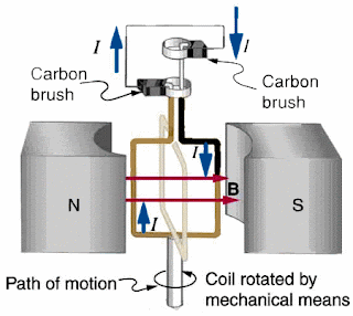
| FIG 1: Basic Concept of Generator |
 |
| FIG 2: Basic Concept of Tranformer |
Typically, transformers are used for "stepping up" the voltage of an electric power source so it can be sent over the grid. By increasing the voltage, one can make each ampere "do more," and it's less energy wasted to send over a long power line. When the current arrives at the distribution substation, transformers step the current down to a commercially viable voltage (e.g., 120V in North America).
Like electric generators/motors themselves, transformers are based on Faraday's law of induction. In an electric generator, a loop of wire is rotated inside a stationary loop with a weak current or (in Figure 1) a magnet. The current in the rotating loop is induced by the change in electromagnetic flux inside it.
After the current is generated, it can induce a current in an adjacent coil. In a toroidal transformer (Figure 1), the two windings do not have any direct contact, but both are wound around an iron core. The primary side, with more loops, has higher voltage and lower amperage than N2 on the secondary side.
In both the case of the transformer and the generator, the induction is magnetic: the primary side, if connected to a power source, introduces a cyclical pulse of voltage, which stimulates a pulse of electromagnetic force, and that stimulates a new pulse of the same frequency.
If the Primary side had DC current, then there would be no induction. In fact, the electromotive force is given by
 where N is the number of windings, 𝛟 is the flux in webers1, and t is the time (generally one calculates this at a point in the cycle. The rate of change in flux is critical in determining the induced EMF.
Transformers are usually very efficient because they require no moving parts. Still, they suffer "copper loss" and "iron loss." Copper loss is lost as heat as current resists going through the windings--which may be great length. Iron loss is caused by the crystalline structure of the iron resisting the reversal of polarity from the induced magnetic flux.
On electrical diagrams, (each phase of) a transformer is indicated thus:

The three lines down the middle signify the iron core, which remains a vital element in the engineering. Certain iron alloys remain essential to the successful implementation of the crucial feature of the transformer, its marriage of electricity and magnetism.2
BASIC TYPES OF TRANSFORMERS
In both the case of the transformer and the generator, the induction is magnetic: the primary side, if connected to a power source, introduces a cyclical pulse of voltage, which stimulates a pulse of electromagnetic force, and that stimulates a new pulse of the same frequency.
If the Primary side had DC current, then there would be no induction. In fact, the electromotive force is given by

Transformers are usually very efficient because they require no moving parts. Still, they suffer "copper loss" and "iron loss." Copper loss is lost as heat as current resists going through the windings--which may be great length. Iron loss is caused by the crystalline structure of the iron resisting the reversal of polarity from the induced magnetic flux.
On electrical diagrams, (each phase of) a transformer is indicated thus:

The three lines down the middle signify the iron core, which remains a vital element in the engineering. Certain iron alloys remain essential to the successful implementation of the crucial feature of the transformer, its marriage of electricity and magnetism.2
BASIC TYPES OF TRANSFORMERS
The toroidal form of transformer is usually quite small; at larger sizes, and larger power loading, the toroidal transformers are not very efficient because of the separation of the primary and secondary windings from each other. Also, the toriodal cores are usually circular now because the magnetic field is prone to escaping via the sharp corners. They are usually used in electronic components to transfer electricity between circuits.
Shell-type transformers use a primary winding inside the secondary winding (the two go opposite directions and are kept separate). The iron core, in this case, wraps around the wired core like the loops of a figure 8 (illustration here, fig. b). These are typically used for very large, powerful transformers.
NOTES
- Webers: a unit of electromagnetic flux; it is given bywhere one multiplies through the rate of change of current (hence, amperes per second per second drops out) and gets a unit of force per unit area. Explaining how flux is calculated, though, is outside of the scope of this post.

- A special thanks to Gottlieb (1998), p.3.
SOURCES 🙵 ADDITIONAL READING
C. van Amerongen, "Transformer," The Way Things Work: an Illustrated Encyclopedia of Technology, New York: Simon 🙵 Schuster (1967)
Irving Gottlieb, Practical Transformer Handbook: for Electronics, Radio and Communications Engineers, Oxford: Newnes/Butterworth-Heinemann (1998) This book is just the best in this or any hypothetical universe.
"Electricity Transmission and Distribution,"America's Energy Future: Technology and Transformation, National Academy of Sciences (2009)
"Transformer Basics and Tutorial," Aspen Core
Labels: electricity, technology


0 Comments:
Post a Comment
<< Home